Hi everyone!
I have trouble solving the Navier-Stokes equations. My system consist of a reactor by which water flows (Q= 5 L min^-1 or 9.7 m s^-1). The reactor dimensions are in mm. The geometry of the reactor was developed with GMSH. I want to solve velocity field (vy, vy). When I run the solver, generate : ERROR:: IterSolve: Failed convergence tolerances.
Could someone tell me where is my mistake?
Here are my geometry and sif files.
Best regards
Cristóbal
Failed convergence tolerances
Re: Failed convergence tolerances
Hi!
I have looked and repeated your case and I have following results (may be I'm wrong, because my experiense of CFD half a year):
https://drive.google.com/open?id=0BycAF ... UZ4dl9aYTg
I have obtained solution with velosity ~0.02 m/s. It is strange, because critical Re=2300 match with velosity = 0.2 m/s. For velosities higher then 0.02 there was no convergence.
p.s. May be someone will help better.
I have looked and repeated your case and I have following results (may be I'm wrong, because my experiense of CFD half a year):
- Reynolds number of your case is about 10600, that means your flow is turbulent. To simulate Steady State folow you need to apply some turbulence model (k-epsilon, for exemple).;
- I have refined the mesh while I tried your case, but for more accurate results you may create the mesh with boundry layer in Gmesh.
- I have applied parabolic velosity profile on inlet.
- I have applied coordinate scaling in sif file
https://drive.google.com/open?id=0BycAF ... UZ4dl9aYTg
I have obtained solution with velosity ~0.02 m/s. It is strange, because critical Re=2300 match with velosity = 0.2 m/s. For velosities higher then 0.02 there was no convergence.
p.s. May be someone will help better.
Re: Failed convergence tolerances
Hello!!
Thank you very much! I appreciate the help.
Thank you very much! I appreciate the help.
-
raback
- Site Admin
- Posts: 4871
- Joined: 22 Aug 2009, 11:57
- Antispam: Yes
- Location: Espoo, Finland
- Contact:
Re: Failed convergence tolerances
Hi,
You could solve the problem also as transient and thereby cover a solution also with the given Reynolds number.
-Peter
You could solve the problem also as transient and thereby cover a solution also with the given Reynolds number.
-Peter
-
kishpishar
- Posts: 54
- Joined: 17 Jun 2015, 10:04
- Antispam: Yes
Re: Failed convergence tolerances
Hi,
Reynolds no. is perhaps not an issue if the case is 2D. Please turn in a turbulence model (k-epsilon) and run the case with the following settings:
Solver 1
Equation = Navier-Stokes
Variable = Flow Solution[Velocity:2 Pressure:1]
Procedure = "FlowSolve" "FlowSolver"
Stabilize = True
Optimize Bandwidth = True
Div Discretization = True
Steady State Convergence Tolerance = 1.0e-2
Nonlinear System Convergence Tolerance = 1.0e-3
Nonlinear System Max Iterations = 1
Nonlinear System Newton After Iterations = 3
Nonlinear System Newton After Tolerance = 0.0
Nonlinear System Relaxation Factor = 0.5
Linear System Solver = Iterative
Linear System Iterative Method = BiCGStabl
Linear System Max Iterations = 1000
Linear System Convergence Tolerance = 1.0e-4
Linear System Preconditioning = ILU0
Linear System Abort Not Converged = False
Linear System Residual Output = 1
Linear System Precondition Recompute = 1
End
Solver 2
Equation = K-Epsilon
Procedure = "KESolver" "KESolver"
Stabilize = True
Optimize Bandwidth = True
Steady State Convergence Tolerance = 1.0e-2
Nonlinear System Convergence Tolerance = 1.0e-3
Nonlinear System Max Iterations = 1
Nonlinear System Newton After Iterations = 3
Nonlinear System Newton After Tolerance = 0.0
Nonlinear System Relaxation Factor = 0.25
Linear System Solver = Iterative
Linear System Iterative Method = BiCGStabl
Linear System Max Iterations = 1000
Linear System Convergence Tolerance = 1.0e-4
Linear System Preconditioning = ILU0
Linear System Abort Not Converged = False
Linear System Residual Output = 1
Linear System Precondition Recompute = 1
End
Equation 1
Name = "Equation 1"
Active Solvers(2) = 1 2
End
Material 1
Name = "Water (room temperature)"
Viscosity Model = K-Epsilon
Viscosity = 1.002e-3
Density = 998.3
End
Initial Condition 1
Name = "InitialCondition 1"
Kinetic Energy = 0.2
Velocity 2 = 0
Kinetic Dissipation = 1.0
Velocity 1 = 0
Velocity 3 = 0
End
-Jay
-
kishpishar
- Posts: 54
- Joined: 17 Jun 2015, 10:04
- Antispam: Yes
Re: Failed convergence tolerances
Also, the Noslip Wall BC = True might result in problems with the k-epsilon model if the boundary layer is not fine enough. Please remove this and change all the walls to something like:
Wall Law = True
Normal-Tangential Velocity = True
Velocity 1 = 0
Boundary Layer Thickness = 0.01
-Jay
Wall Law = True
Normal-Tangential Velocity = True
Velocity 1 = 0
Boundary Layer Thickness = 0.01
-Jay
Re: Failed convergence tolerances
Hello!!
Sorry for the delay in answering, I read the contributions and I appreciate the assistance given.
The results I get are those shown in Figure Velocity_abs and Velocity_x. The conditions under which it were calculated are those in SIF archive.
The question is, the results are correct?
On the other hand, I want to implement the k-epsilon model to solve the system with turbulent flow, however, I could not implement it, elmersolver throws ERROR:: ComputeChange: Norm of solution exceeded given bounds. Attached files for review (ReIgual10000.zip).
Thank you very much.
- Attachments
-
- ReIgual10000.zip
- (60.38 KiB) Downloaded 321 times
-
- case.sif
- (3.06 KiB) Downloaded 344 times
-
- Velocity_x.jpg (11.83 KiB) Viewed 9129 times
Re: Failed convergence tolerances
Hi, dear Cristobal!
In incompressible flow inlet and outlet velocities have to be equal. That is not observed on specified picture. So, we have to do something.
I played around with Cristobal's reactor and I want to share the results. I have prepared a non-GUI case and obtained the results.
First of all I have prepared a template to calculate inlet values of kinetic energy kinetic dissipation and boundary layer thickness that can be placed at the top of SIF file.
The algorithm is following:
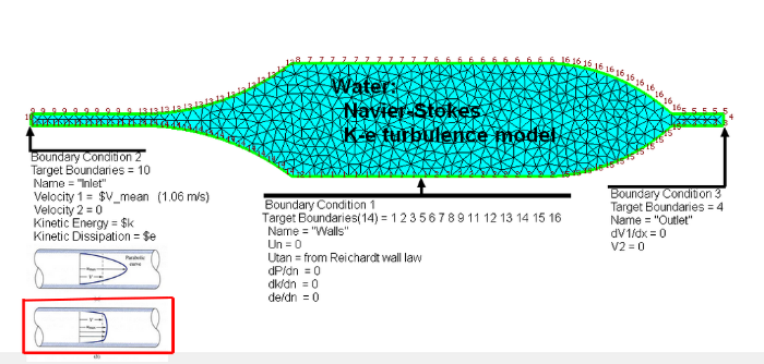
Cristobal's problem at one picture:
SIF file:
Some comments:
1) The mesh of reactor is coarse to capture boundary viscous effects. So we use wall law (according to kishpishar advise). In this case Elmer models only turbulent core of flow. Wall boundaries of our domain represents the boundary where viscous layer transits to turbulent core (0.99% boundary https://en.wikipedia.org/wiki/Boundary_layer_thickness). We use normal-tangential coords. at walls, such that velocity normal to boundary is 0. Tangential velocity on wall is calculated from wall function by Elmer automatically. The rest of BCs are shown at pic. above.
2) I use direct linear solver for 2D cases: it is reliable and there's enough memory for 2D case.
3) The mesh was refined by
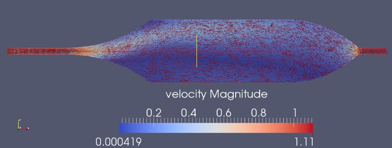
Results:
Velocity
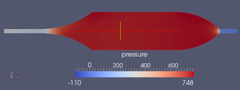
Pressure
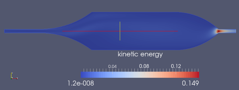
Kinetic energy
Dissipation rate
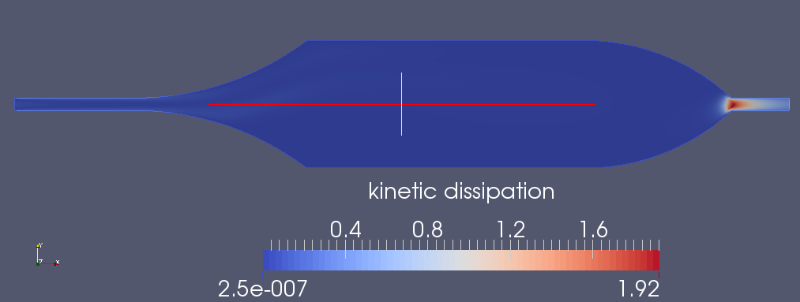
Conclusions:
Convergence was reached after 43 SS iterations. According to pictures above we see one big vortex. Main flow is placed at upper part of reactor and lower part cyclically rotates along the symm axis. So, Cristobal, I have a question to you. Is your reactor has cylinder shape or it is just extrusion of this profile? If it is extrusion, then simulation is valid, else cylindrical coords. are to be used or full 3D simulation. I guess, in last case results will be more symmetrical.
P.S. If some thermal coupling is planning (or another phenomena at boundary), you should make proper mesh with near wall refinement. In this case no-slip wall condition are to be utilized.
Full project is in attachment:
In incompressible flow inlet and outlet velocities have to be equal. That is not observed on specified picture. So, we have to do something.
I played around with Cristobal's reactor and I want to share the results. I have prepared a non-GUI case and obtained the results.
First of all I have prepared a template to calculate inlet values of kinetic energy kinetic dissipation and boundary layer thickness that can be placed at the top of SIF file.
Code: Select all
!----------------------------------------------------
!Parameters of fluid
!----------------------------------------------------
$rho = 998.0  ! kg/m^3
$mu = 0.00101  ! Pa*s
!----------------------------------------------------


!----------------------------------------------------
!Parameters of inlet velocity profile and inlet geometry
!----------------------------------------------------
$V_mean= 1.06  ! m/s mean inlet velocity
$R_inlet = 0.005  ! m radius of inlet tube
$x_inlet = 0.05 ! distance downstream from the start of the boundary layer, m
$D_inlet = R_inlet * 2  ! m
!----------------------------------------------------


!----------------------------------------------------
!Parameters of K-Epsilon model
!----------------------------------------------------
$Re_d = rho * V_mean * D_inlet / mu  ! Reynolds number
$Re_x = rho * V_mean * x_inlet / mu  ! Reynolds downstream number
$LS = 0.038 * D_inlet  ! Turbulence length scale
$I = 0.16 * pow(Re_d, -0.125)  ! Turbulence intensity

$k = 3 * pow(V_mean * I, 2) / 2  ! Turbulent kinetic energy
$e = 0.09 * pow(k, 1.5) / LS  ! Turbulence Dissipation rate
$blt = 0.37 * x_inlet / pow(Re_x, 0.2) ! m boundary layer thickness
!----------------------------------------------------
- Input fluid density
- Input fluid viscosity
- Input mean velocity
- Input radius of inlet tube
- Input length of inlet channel downstream
- Calculate inlet tube diameter
- Calculate Reynolds number (http://www.cfd-online.com/Wiki/Reynolds_number)
- Calculate downstream Reynolds number (https://en.wikipedia.org/wiki/Boundary_layer_thickness)
- Calculate turbulence length scale (http://www.cfd-online.com/Wiki/Turbulent_length_scale)
- Calculate turbulence intensity (http://www.cfd-online.com/Wiki/Turbulence_intensity)
- Calculate turbulent kinetic energy (http://www.cfd-online.com/Wiki/Turbulen ... conditions)
- Calculate turbulence dissipation rate (http://www.cfd-online.com/Wiki/Turbulen ... conditions)
- Calculate boundary layer thickness (https://en.wikipedia.org/wiki/Boundary_layer_thickness)
Cristobal's problem at one picture:

SIF file:
Code: Select all
!----------------------------------------------------
!Parameters of K-Epsilon model
!----------------------------------------------------
$rho = 1000.0
$mu = 0.001

$V_mean = 1.06
$k = 0.00425222746826
$e = 0.0656725145933
$blt = 0.00210047034525
!----------------------------------------------------


Header
  CHECK KEYWORDS Warn
  Mesh DB "." "."
  Include Path ""
  Results Directory ""
End

Simulation
  Max Output Level = 5
  Coordinate System = Cartesian
  Coordinate Mapping(3) = 1 2 3
  Simulation Type = Steady state
  Steady State Max Iterations = 200
  Output Intervals = 1
  Timestepping Method = BDF
  BDF Order = 1
  Solver Input File = case.sif
  Post File = case.ep
  !--------------------------
  Coordinate scaling = 0.001
  !Mesh Levels = 3
  !--------------------------
End


Body 1
  Target Bodies(1) = 1
  Name = "Reactor"
  Equation = 1
  Material = 1
  Initial condition = 1
End


Solver 1
  Exec Solver = Always
  Equation = Navier-Stokes
  Procedure = "FlowSolve" "FlowSolver"
  Variable = Flow Solution[Velocity:2 Pressure:1]
  Stabilize = True
  Bubbles = False
  Lumped Mass Matrix = False
  Optimize Bandwidth = True
  Steady State Convergence Tolerance = 1.0e-4
  Nonlinear System Convergence Tolerance = 1.0e-5
  Nonlinear System Max Iterations = 1
  Nonlinear System Newton After Iterations = 100
  Nonlinear System Newton After Tolerance = 0
  Nonlinear System Relaxation Factor = 0.7
  Linear System Solver = direct
  Linear System Direct Method = umfpack
  Linear System Convergence Tolerance = 1.0e-6
End

Solver 2
  !Exec Solver = never
  Equation = K-Epsilon
  Procedure = "KESolver" "KESolver"
  Stabilize = True
  Bubbles = False
  Lumped Mass Matrix = False
  Optimize Bandwidth = True
  Steady State Convergence Tolerance = 5.0e-3
  Nonlinear System Convergence Tolerance = 1.0e-6
  Nonlinear System Max Iterations = 1
  Nonlinear System Newton After Iterations = 100
  Nonlinear System Newton After Tolerance = 0
  Nonlinear System Relaxation Factor = 0.5
  Linear System Solver = direct
  Linear System Direct Method = umfpack
  Linear System Convergence Tolerance = 1.0e-6
End

Solver 3
  Exec Solver = after all
  Equation = "result output"
  Procedure = "ResultOutputSolve" "ResultOutputSolver"
  Vtu Format = Logical True
End


Equation 1
  Name = "Ecuaciones de Flujo"
  Active Solvers(3) = 1 2 3
End


Material 1
  Name = "Water (room temperature)"
  Density = $rho
  Viscosity = $mu
  Viscosity Model = K-Epsilon
  KE Clip = 1.0e-6
End


Initial Condition 1
  Name = "Initial Guess"
  Velocity 1 = $V_mean/2
  Velocity 2 = 0
  Kinetic Energy = 0.0001
  Kinetic Dissipation = 1e-4
End


Boundary Condition 1
  Target Boundaries(14) = 1 2 3 5 6 7 8 9 11 12 13 14 15 16
  Name = "Walls"
  Normal-Tangential Velocity = True
  Velocity 1 = 0
  Wall Law = True
  Boundary Layer Thickness = $blt
End

Boundary Condition 2
  Target Boundaries = 10
  Name = "Inlet"
  Velocity 1 =  $V_mean
  Velocity 2 = 0
  Kinetic Energy = $k
  Kinetic Dissipation = $e

End

Boundary Condition 3
  Target Boundaries = 4
  Name = "Outlet"
  Velocity 2 = 0
End1) The mesh of reactor is coarse to capture boundary viscous effects. So we use wall law (according to kishpishar advise). In this case Elmer models only turbulent core of flow. Wall boundaries of our domain represents the boundary where viscous layer transits to turbulent core (0.99% boundary https://en.wikipedia.org/wiki/Boundary_layer_thickness). We use normal-tangential coords. at walls, such that velocity normal to boundary is 0. Tangential velocity on wall is calculated from wall function by Elmer automatically. The rest of BCs are shown at pic. above.
2) I use direct linear solver for 2D cases: it is reliable and there's enough memory for 2D case.
3) The mesh was refined by
Code: Select all
Mesh Levels = 3Velocity

Pressure

Kinetic energy

Dissipation rate

Conclusions:
Convergence was reached after 43 SS iterations. According to pictures above we see one big vortex. Main flow is placed at upper part of reactor and lower part cyclically rotates along the symm axis. So, Cristobal, I have a question to you. Is your reactor has cylinder shape or it is just extrusion of this profile? If it is extrusion, then simulation is valid, else cylindrical coords. are to be used or full 3D simulation. I guess, in last case results will be more symmetrical.
P.S. If some thermal coupling is planning (or another phenomena at boundary), you should make proper mesh with near wall refinement. In this case no-slip wall condition are to be utilized.
Full project is in attachment:
- Attachments
-
- reactor k-e case.7z
- (261.38 KiB) Downloaded 332 times
Re: Failed convergence tolerances
Hi Dmitry,
Appreciable demonstration of a numerical example in fluid mechanics. Hats off to your efforts.
Yours Sincerely,
Anil Kunwar
Appreciable demonstration of a numerical example in fluid mechanics. Hats off to your efforts.
Yours Sincerely,
Anil Kunwar
Anil Kunwar
Faculty of Mechanical Engineering, Silesian University of Technology, Gliwice
Faculty of Mechanical Engineering, Silesian University of Technology, Gliwice
Re: Failed convergence tolerances
Yor're welcome Anil
In addition to previous post I'd like to share transient version of sif. Quite funny results obtained. First the flow moves forward and symmetrically. I thought previous steady simulation is wrong... But after thinking some time the flow decides where to go. With different settings it goes up or down.
I checked in steady case. Also, being changed solver settings, flow may choose different way.
Here the SIF for transient simulation:
Code: Select all
!----------------------------------------------------
!Parameters of K-Epsilon model
!----------------------------------------------------
$rho = 1000.0
$mu = 0.001

$V_mean = 1.06
$k = 0.00425222746826
$e = 0.0656725145933
$blt = 0.00210047034525
!----------------------------------------------------


Header
  CHECK KEYWORDS Warn
  Mesh DB "." "."
  Include Path ""
  Results Directory ""
End

Simulation
  Max Output Level = 5
  Coordinate System = Cartesian
  Coordinate Mapping(3) = 1 2 3
  Simulation Type = Transient
  Steady State Max Iterations = 1
  Output Intervals = 1
  Timestepping Method = BDF
  BDF Order = 3
  Timestep intervals = 300
  Timestep sizes = $60/300
  Solver Input File = case.sif
  Post File = case.ep
  !--------------------------
  Coordinate scaling = 0.001
  Mesh Levels = 3
  !--------------------------
End


Body 1
  Target Bodies(1) = 1
  Name = "Reactor"
  Equation = 1
  Material = 1
  Initial condition = 1
End


Solver 1
  Exec Solver = Always
  Equation = Navier-Stokes
  Procedure = "FlowSolve" "FlowSolver"
  Variable = Flow Solution[Velocity:2 Pressure:1]
  Stabilize = True
  Bubbles = False
  Lumped Mass Matrix = False
  Optimize Bandwidth = True
  Steady State Convergence Tolerance = 1.0e-4
  Nonlinear System Convergence Tolerance = 1.0e-5
  Nonlinear System Max Iterations = 1
  Nonlinear System Newton After Iterations = 100
  Nonlinear System Newton After Tolerance = 0
  Nonlinear System Relaxation Factor = 0.7
  Linear System Solver = direct
  Linear System Direct Method = umfpack
  Linear System Convergence Tolerance = 1.0e-6
End

Solver 2
  !Exec Solver = never
  Equation = K-Epsilon
  Procedure = "KESolver" "KESolver"
  Stabilize = True
  Bubbles = False
  Lumped Mass Matrix = False
  Optimize Bandwidth = True
  Steady State Convergence Tolerance = 5.0e-3
  Nonlinear System Convergence Tolerance = 1.0e-6
  Nonlinear System Max Iterations = 2
  Nonlinear System Newton After Iterations = 100
  Nonlinear System Newton After Tolerance = 0
  Nonlinear System Relaxation Factor = 0.5
  Linear System Solver = direct
  Linear System Direct Method = umfpack
  Linear System Convergence Tolerance = 1.0e-6
End

Solver 3
  Exec Solver = after timestep
  Equation = "result output"
  Procedure = "ResultOutputSolve" "ResultOutputSolver"
  Vtu Format = Logical True
End


Equation 1
  Name = "Ecuaciones de Flujo"
  Active Solvers(3) = 1 2 3
End


Material 1
  Name = "Water (room temperature)"
  Density = $rho
  Viscosity = $mu
  Viscosity Model = K-Epsilon
  KE Clip = 1.0e-6
End


Initial Condition 1
  Name = "Initial Guess"
  Velocity 1 = $V_mean/2
  Velocity 2 = 0
  Kinetic Energy = 0.0001
  Kinetic Dissipation = 1e-4
End


Boundary Condition 1
  Target Boundaries(14) = 1 2 3 5 6 7 8 9 11 12 13 14 15 16
  Name = "Walls"
  Normal-Tangential Velocity = True
  Velocity 1 = 0
  Wall Law = True
  Boundary Layer Thickness = $blt
End

Boundary Condition 2
  Target Boundaries = 10
  Name = "Inlet"
  Velocity 1 = $V_mean
  Velocity 2 = 0
  Kinetic Energy = $k
  Kinetic Dissipation = $e

End

Boundary Condition 3
  Target Boundaries = 4
  Name = "Outlet"
  Velocity 2 = 0
End