Magnetic field with symmetry planes

Numerical methods and mathematical models of Elmer
tobin
Posts: 7
Joined: 31 Mar 2023, 06:46
Antispam: Yes

Magnetic field with symmetry planes

Post by tobin »

Hi folks,

I am evaluating Elmer as a tool for modelling electromagnets for accelerators. I have access to commercial FEM software to compare.

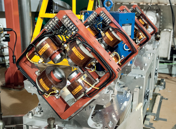
As a relatively simple test case, I am running a simple model of a quadrupole magnet like this one:
Image

I have attached a mesh, case file and a BH curve — this should be everything needed to run the simulation. The mesh is reasonably coarse at the moment, just to make things smaller and faster for troubleshooting.

I am trying to model a quarter of the geometry, since there is symmetry on the ZX and ZY planes. These should have a "normal magnetic" boundary condition, to force flux to pass the boundary at exactly 90 degrees. This is also called the "homogeneous Neumann boundary condition". I believe this is the default ("natural") boundary condition in WhitneyAV, so I have not prescribed anything in the SIF file.

However, if I plot the field, I find that the tangential components of the flux at the boundary are not zero. Here is my solution and a plot of the field from (x,y,z) = (15mm, 0mm, 0mm) to (15mm, 15mm, 0mm). Notice that at y=0, the component Bx is quite different from zero. It gets better with a finer mesh, but is still unusually large, I think.
paraview_line.png
paraview_line.png (83.34 KiB) Viewed 1076 times
The field values away from the boundary seem okay, for example here I am plotting field integrals (Calculated per the python code in this post) vs angle at a radius of 25mm. I am comparing the Elmer solution to the same geometry solved using Opera. Notice the errors at the boundary — the Opera integrals are ~0, but the Elmer ones are not:
integral_fields.png
integral_fields.png (12.76 KiB) Viewed 1077 times
I am probably doing silly things, feel free to tell me I'm doing it all wrong! I would love some ideas about how I could make the Elmer solution better at the symmetry boundaries.
Attachments
Elmer.zip
(959.21 KiB) Downloaded 55 times
hielau
Posts: 12
Joined: 26 Sep 2017, 19:18
Antispam: Yes

Re: Magnetic field with symmetry planes

Post by hielau »

Hi,

You could try to add anti periodic boundary condition to those boundaries. Take a look chapter 9 of solver manualhttp://www.nic.funet.fi/pub/sci/physics ... Manual.pdf

Split the boundary into two separate boundaries.
boundary.png
boundary.png (51.33 KiB) Viewed 1070 times

Code: Select all

Boundary Condition 2
  Name = Perpendicular1
  Anti Periodic BC = Integer 3
End

Boundary Condition 3
  Name = Perpendicular2
End
or maybe Mortar BCs could be used

Code: Select all

Solver 2
  ...
  Apply Mortar BCs = Logical True
  ...
End

Boundary Condition 2
  Name = Perpendicular1
  Mortar BC = Integer 3
  Mortar BC Static = Logical True
  Radial Projector = Logical True
End

Boundary Condition 3
  Name = Perpendicular2
End
raback
Site Admin
Posts: 4838
Joined: 22 Aug 2009, 11:57
Antispam: Yes
Location: Espoo, Finland
Contact:

Re: Magnetic field with symmetry planes

Post by raback »

Hi

Really nice case you have there! I appreciate the diligent comparison.

The value of B at the boundary will have limited accuracy since it is computed from a low order potential solution of A. Quadratic approximation for the AV solver could help, but with a price. For lowest order edge elements the derivative is constant within each element. The "Discontinuous Bodies" helps in averaging the solution over all hits to the nodes. So the middle of the material the evaluation of B at nodes gets contribution from all sides while in the extrema the averaging is one-sided only.

The averaging on BCs could in fact be also done implicitely in the CalcFields solver when "calculate nodal fields = true" if you "apply mortar bcs = true" there. Now unfortunately the CalcFields solver computes vector fields one components at a time so this is not a remedy. If you had 180 deg piece then each component would be antiperiodic.

The vector potential is presented with edge elements so the limitations above do apply there. You could really use mortar BCs to enforce continuity as explained by "hielau". However, if the natural BC really do apply you don't get any benefit. My suspicion is that this is mainly a postprocessing issue. If there would be other issues as well one would think that the results would differ elsewhere too.

Generally the elemental fields is the right choice when you have jumps. Without jumps the nodal fields are better since they present the true fitting of the visualized field using the Galerkin method. If you have jumps then then enforcing the nodal fields to be continuous corrupts them.

To conclude: try "quadratic approximation = true".

-Peter
fjimenez
Posts: 63
Joined: 27 Sep 2021, 23:40
Antispam: Yes

Re: Magnetic field with symmetry planes

Post by fjimenez »

Hi,

Nice case you have here. I am very pleased to see Elmer compares very well against Opera. I've done some work validating symmetry planes and symmetry boundary conditions and I have had great results from Elmer. Unfortunately I don't have access to paid software so I've used only FEMM, some simple theory,
and in some cases, experiments. I usually use AV {e} = 0 (and AV = 0 if I have eddy currents) at the boundary but this case is different because this one needs "anti-symmetry" boundary conditions to put it a name. It is very interesting that this type of boundary conditions can also work by just using simple natural bc. I added a rendering of your case at the end just for fun. I think mortar BCs, as hielau suggested, will help improve the field at the boundaries, Peter already explained the problem with this approach, and he really is the expert. I did some work some time ago with Mortar BCs but they never work for me in cases that needed symmetry BC, but I was probably doing something wrong at the time. I recall that anti-symmetry BC were working quite well so it is worth a try. I can take a stab at it if you share your mesh with the symmetry planes broken apart into two surfaces.
figure1_s.png
figure1_s.png (274.41 KiB) Viewed 1046 times
Cheers,
tobin
Posts: 7
Joined: 31 Mar 2023, 06:46
Antispam: Yes

Re: Magnetic field with symmetry planes

Post by tobin »

Thanks so much for the interest and helpful replies! I am happy to keep sharing comparisons if there continues to be interest.

So, I have updated the mesh to split the boundary condition. I have also included the original STEP file and gmsh GEO file. The commands I am using to completely mesh and run the simulation are:

Code: Select all

gmsh "model.geo" -3 -format "msh2" -optimize_netgen -clscale 3 -o "MESH.msh"
ElmerGrid.exe 14 2 "MESH.msh" -autoclean
ElmerSolver.exe case.sif

The clscale parameter can be reduced for a finer mesh. Below are my results from trying the suggestions:


Antiperiodic boundary condition.
I looked into the referenced section of the manual and made my boundary conditions like so:

Code: Select all

Boundary Condition 2
  Name = "YZPlane"
  Anti Periodic BC = Integer 3
End

Boundary Condition 3
  Name = "XZPlane"
End
— but this seemed to give an identical solution to the natural boundary condition. I also noticed in the solver logs the line "CheckKeyword: Unlisted keyword: [anti periodic bc] in section: [boundary condition 2]"
This makes me think that the BC wasn't actually applied? Perhaps I am missing something?


Mortar boundary condition.
When I tried the mortar BCs like so:

Code: Select all

Boundary Condition 2
  Name = "YZPlane"
  Mortar BC = Integer 3
  Mortar BC Static = Logical True
  Radial Projector = Logical True
End

Boundary Condition 3
  Name = "XZPlane"
End
I get the error "WARNING:: LevelProjector: Target mesh has too much skew, using generic integrator when needed! ERROR:: LevelProjector: We cannot use fully strong projector as wished in this geometry!"

If I omit the "Radial Projector" line, then it solves successfully. The result seems -- as far as I can tell -- exactly the
same as the "natural BC" solution. I also notice these lines in the logs: "PeriodicProjector: Weighted projector is very suboptimal, do not use it! WARNING:: PeriodicProjector: Use "Normal Projector" or "Level Projector" instead!"


Quadratic approximation.
This was suggested by Peter. I added the following to my sif file:

Code: Select all

Solver 2
  Equation = MGDynamics
  Procedure = "MagnetoDynamics" "WhitneyAVSolver"
  
  Quadratic Approximation = True
  ...
Unfortunately this causes the solver to not converge:

510 0.5660E+09 0.6758E+15
520 0.3327E+09 0.3972E+15
530 0.1884E+10 0.2250E+16
540 0.2011E+14 0.2401E+20
550 0.3915E+13 0.4674E+19
BiCGStabl robust: 553 0.8902E+00 1 0.1707E+15 0.2039E+21
ERROR:: IterSolve: Numerical Error: System diverged over maximum tolerance.
STOP 1

And I'm not sure how that might be fixed.
Attachments
Quadrupole_splitBC.zip
(974.02 KiB) Downloaded 51 times
fjimenez
Posts: 63
Joined: 27 Sep 2021, 23:40
Antispam: Yes

Re: Magnetic field with symmetry planes

Post by fjimenez »

Hi,

Please keep sharing comparisons with Opera, I think this type of work is very important to increase Elmer's reputation for electromagnetic
simulations.

I will play with the mesh you uploaded and report back later. One more thing, I think you need a mesh with quadratic elements to use the quadratic approximation
flag but I might be mistaken. You can create a quadratic mesh with ElmerGrid using the -increase flag, it might be worth a try with your original, coarser mesh.
Also, I think you also need to add the save linear elements flag to the ResultOutputSolver so you can read the vtu file in Paraview.

Cheers,
tobin
Posts: 7
Joined: 31 Mar 2023, 06:46
Antispam: Yes

Re: Magnetic field with symmetry planes

Post by tobin »

Thanks for that pointer, fjimenez! I can now get the quadratic solution to solve and -- sure enough -- it dramatically improves the solution at the boundary.Here is the same plot as above showing that the tangential components disappear at the symmetry plane:
Screenshot 2023-04-05 222947.png
Screenshot 2023-04-05 222947.png (85.26 KiB) Viewed 1017 times
I am currently chasing down one mystery: some weird outliers that show up in the integrals now, but not on the boundary. They seem strangely discontinuous. I will investigate further and report back when I have more.
download.png
download.png (11.41 KiB) Viewed 1017 times
Apart from that, the differences with Opera are now <1%, which seems like a decent start! I'll see if some careful work (on both models) can reduce that further. I'm interested to eventually see if it's possible to get agreement closer to the 1e-4 level, since accelerator magnets are often designed to that level.
raback
Site Admin
Posts: 4838
Joined: 22 Aug 2009, 11:57
Antispam: Yes
Location: Espoo, Finland
Contact:

Re: Magnetic field with symmetry planes

Post by raback »

Hi

Just a note to the linear/quadratic elements. Only the standard Lagrange elements take use of the additional nodes it the mesh. This is the classical way in finite elements to improve the local accuracy. However, for the AV solver there is a combination of basis functions. The A is solved using the Hcurl conforming elements that for the lowest order they have just one degree of freedom for each edge. The approximation for V is nodal one and it is independent of the basis for A. You can see these in element defenitions starting from line 115 in:
https://github.com/ElmerCSC/elmerfem/bl ... Solver.F90

For example, when we have one nodal dof for V and one edge dof for A we have:
ElemType = "n:1 e:1"

Whereas no V and 2nd order Hcurl elements we have:
ElemType = "n:0 e:2 -brick b:6 -pyramid b:3 -prism b:2 -quad_face b:4 -tri_face b:2"

So in addition to 2 dofs related to each edge we have for example 6 bubbles inside each hexahedral element...

Edit: as it seems that the 2nd order nodal element was significant improvement I think it relates to the postprocessing part. Maybe you can check whether the norm after AV solver really changed or if only the results of the postprocessing changed. Or it could also be related to the way the current density is obtained. That could be somewhat more accurate and hence given better results. It was somewhat a surprice to me but a very welcome one! Just need to understand what is the reason... Do you have solve for the scalar potential? Then the variable "AV" should be nonzero.

-Peter
raback
Site Admin
Posts: 4838
Joined: 22 Aug 2009, 11:57
Antispam: Yes
Location: Espoo, Finland
Contact:

Re: Magnetic field with symmetry planes

Post by raback »

Ok, I seem to have omitted the fact that you used both the "-increase" and "quadratic approximation" raising both the classical nodal order and the edge elements order. Just doing the latter was not enough. Apparently the "jfix" potential needs to solved with quadratic elements to effectively eliminate the divergence of the current density since otherwise convergence is not obtained. I don't think I've seen this effect that clearly before!! -Peter
tobin
Posts: 7
Joined: 31 Mar 2023, 06:46
Antispam: Yes

Re: Magnetic field with symmetry planes

Post by tobin »

Thank you for the detailed replies, Peter. I am not an expert in the internals of FEM solvers so some of that went a bit over my head. I'm more an FEM user who knows enough to get into trouble! That said, I think I broadly follow what you're saying and will try to learn more as I go.

For the moment, I will report that yes, those results were with both "-increase" and "Quadratic Approximation".
  • When I use "Quadratic Approximation" but not "-increase": The WhitneyAV solution does not converge (I think this may be caused by the currrent flow solution having non-zero divergence, like Peter said.)
  • When I use "-increase" but not "Quadratic Approximation": The WhitneyAV solver complains "ERROR:: GetEdgeBasis: Can't handle but linear elements, sorry."
Finally, I have tracked down the location of the strange outliers I mention in my previous post. There seem to be issues with the mesh or the VTU output. I have uploaded the input mesh and the VTU output here. Tf I open that VTU in Paraview and drop a "Probe Location" at a point (x,y,z) = (0.024972246, 0.001177661, -0.034), The values are all zero and "vtkValidPointMask" is zero. This suggests a mesh problem, I think. I vaguely suspect the "-increase" in ElmerGrid might have something to do with this, but it's only a hunch at this point.

This also affects me when I use VTK directly from Python, which is how I'm computing the field integrals.

If anyone has any ideas about my "vtkValidPoint" problem, I would appreciate it as I'm a little bit lost on how to debug this from here.

Cheers, and happy Easter.
Post Reply